Material Context and Test-Piece Planning
A line-art concept can look resolved long before it is ready for a material-specific laser engraving test. The preview may show contour, spacing, and placement, but it does not show how a particular surface, machine, process, or finish will respond.
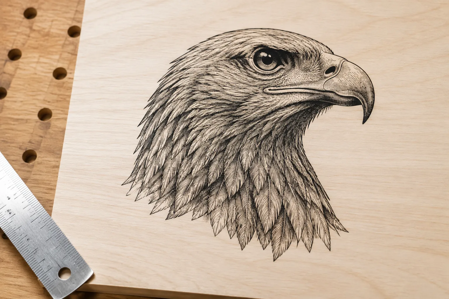
The immediate task is to turn the concept into a documented test-piece brief. That brief should state what the artwork must demonstrate, which choices remain provisional, what the shop needs to verify, and who owns the next decision.
A useful plan separates four layers:
- Concept intent: what the artwork should communicate.
- Material context: which surface and object are being considered.
- Shop verification: what the fabricator needs to test.
- Production approval: what must be accepted after the physical result is reviewed.
This boundary keeps an attractive mockup from being mistaken for output evidence. It also gives the shop a more useful question than “Will this engrave well?”
What the Test Needs to Resolve
A test piece earns its place when it addresses a specific uncertainty. It does not need to reproduce the entire production object, but it should include the features most likely to affect the decision.
| Question | Visible feature to include | Decision it may support |
|---|---|---|
| Will important marks remain distinct? | Thinnest stroke and repeated lines | Retain, widen, or simplify the line work |
| Will negative space remain open? | Smallest gap, counter, and bridge | Change scale, spacing, or detail |
| Will the mark read on the surface? | Representative contour and tonal area | Review contrast and viewing distance |
| Does placement affect the result? | Edge, curve, grain direction, coating, or surface transition | Reposition, match the test surface, or ask for another sample |
| Are visible differences acceptable? | Logo, symbol, or line-art fragment at intended scale | Approve, revise, or identify an unresolved process question |
The result must be interpreted against the actual material and equipment context. A sample from another surface or machine may help frame a question, but it should not be treated as a transferable setting or prediction.
Keep the Artifacts Separate
| Artifact | What it can show | What it cannot establish |
|---|---|---|
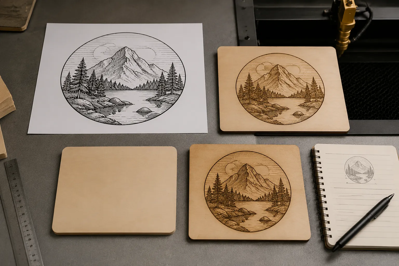
| Concept preview | Composition, line direction, relative scale, and visual emphasis | Physical contrast, edge behavior, or material response |
| Material-context mockup | How the concept relates visually to a named surface or object | Actual engraved appearance or verified machine performance |
| Planned test piece | The artwork features and questions selected for verification | A physical result that has not yet been produced |
| Documented shop sample | Observed output under recorded conditions | Universal settings or performance on another setup |
| Production approval file | The artwork and context accepted for the stated job | Suitability for another material, machine, finish, or application |
Use status labels that travel with the files. “Oak mockup,” “planned test,” “sample record,” and “approved production artwork” describe different states and should not be used interchangeably. A path view can show that contours, counters, bridges, and gaps exist in the artwork; it cannot show whether the surface will preserve them at the intended scale.
Record the Material Context
The material name alone is not enough for a useful handoff. Record the surface that will actually receive the mark, including details that could change the test question.
- Material type, product name, supplier, and batch information where available.
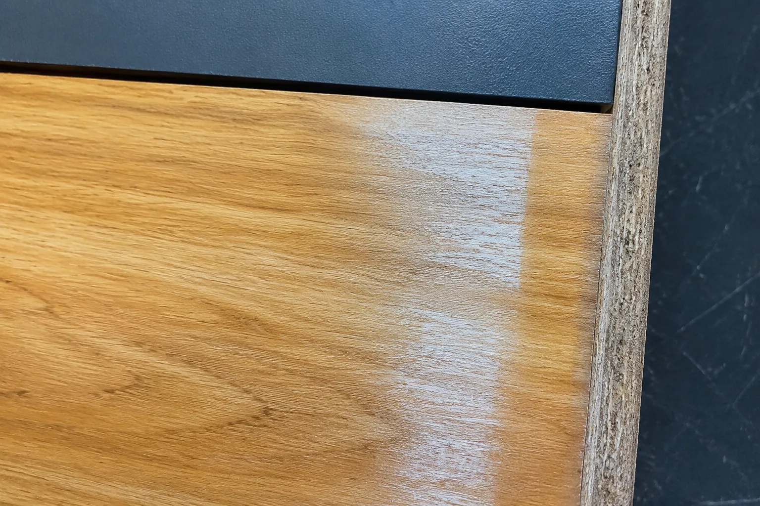
- Surface finish, coating, preparation, and visible condition.
- Thickness and approximate object dimensions.
- Flat, curved, edged, or irregular placement.
- Grain direction or other visible surface orientation where relevant.
- Intended application, viewing distance, artwork scale, and placement.
- Whether the test uses the final object or a matched test part.
- Whether the marking objective is a surface mark, contrast change, or material removal.
Research and technical documentation can demonstrate why these fields matter, but examples remain limited to their stated material, equipment, artwork, and process. Their value here is the discipline of recording context, not a general prediction about line-art output.
Manufacturer documentation can provide useful terminology for material compatibility and applications. A listed material category remains a checkpoint for investigation. It does not establish identical behavior across machines, formulations, coatings, surfaces, or finished objects.
Build a Compact Test Matrix
A compact laser engraving test matrix connects controlled changes with visible questions. It should be small enough to compare and specific enough to explain what each sample is meant to reveal.
Start with the artwork features that matter most:
- Stroke width, gap width, and counter size.
- Corner sharpness and contour density.
- Overall mark scale and repeated spacing.
- Placement near an edge, curve, grain change, or surface transition.
- A representative logo, symbol, or line-art fragment.
Then record the outcome using stable fields:
| Field | Planning purpose |
|---|---|
| Test ID | Connects the sample, photographs, artwork revision, and decision record |
| Artwork feature and scale | Identifies the question being tested at the intended size |
| Material, surface, and placement | Prevents context loss |
| Shop-selected process context | Records what the fabricator actually used without prescribing settings |
| Visible result | Describes continuity, contrast, edges, gaps, and surface changes |
| Defect or difference | Names the issue that may require a design or process decision |
| Interpretation status | Separates observation from an unverified explanation |
| Next owner | Assigns the follow-up decision |
The matrix should record process variables selected by the shop and its equipment documentation. Power, speed, passes, focus, resolution, pulse behavior, and related settings depend on the specific setup. The Root planning task is to identify what must be recorded, not to prescribe a universal combination.
Document the Sample and Its Limits
A documented laser engraving test-piece record should let a later reviewer identify what was actually tested. It does not need to make the result universal. It needs to prevent the result from being detached from its conditions.
- Test date, record identifier, and artwork file revision.
- Material identity, supplier, surface condition, finish, and preparation.
- Test-piece dimensions, object dimensions, and intended placement.
- Artwork scale, location, and marking objective.
- Machine identity and relevant equipment context.
- Shop-selected process variables and the order of test runs.
- Photograph conditions used for comparison.
- Visible findings, unresolved questions, reviewers, and approval owner.
A stable naming pattern can connect the records:
project-material-surface-artwork-revision-test-id
The exact convention matters less than preserving the connection between artwork revision, sample, photographs, and decision record. “Dark mark on wood” is too broad to support later review. “Sample T03 shows a darker edge on the narrow contour near the upper placement boundary” identifies the visible location while leaving the cause open for shop investigation.
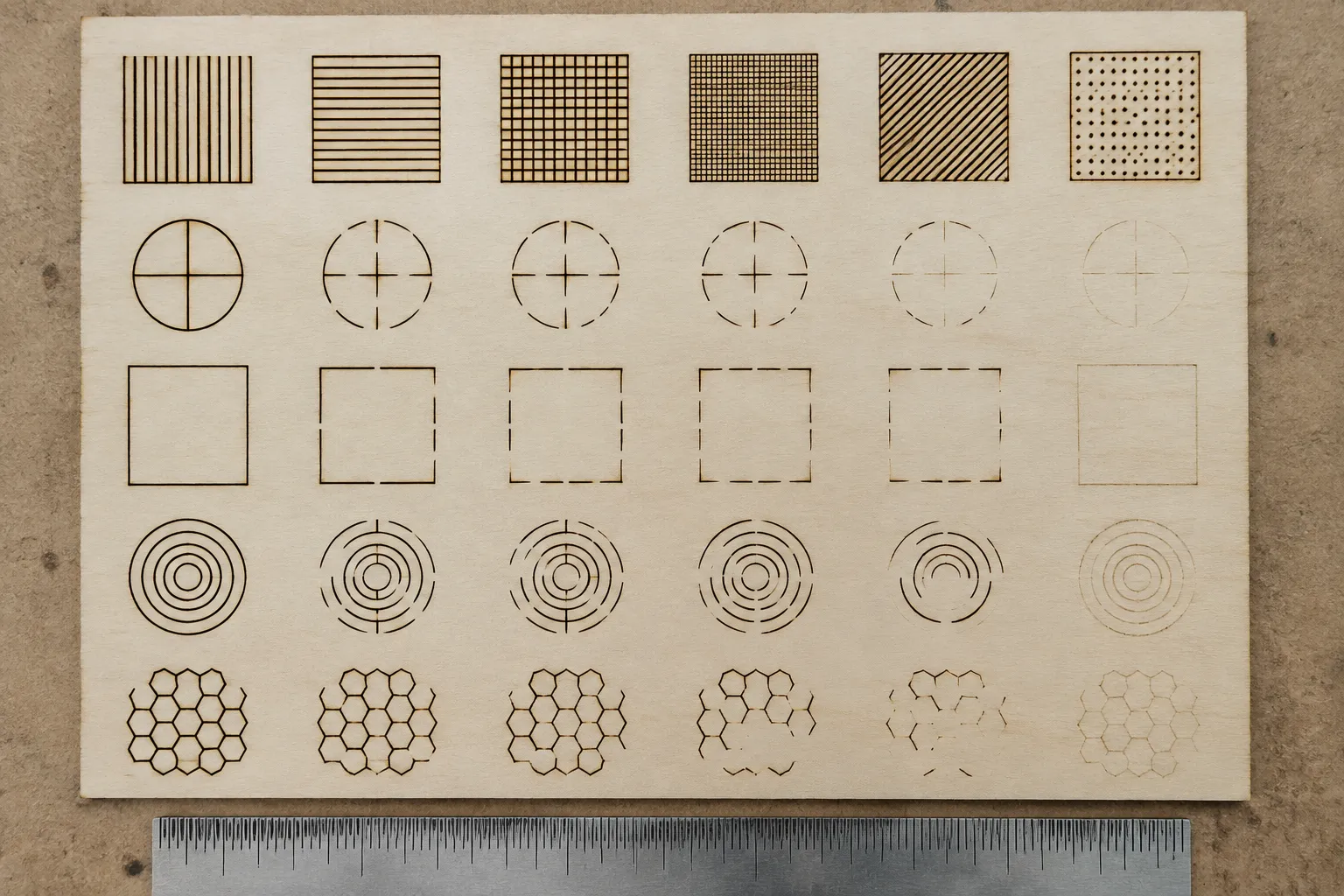
For photographed laser engraving samples, keep camera position, framing, lighting, focus, surface orientation, and reference scale consistent where practical. Describe what is visible before suggesting why it happened. “The narrow gap appears closed” is an observation; assigning a process cause requires verification from the actual setup.
Review Differences Against the Job
A defect is not simply any difference from the digital preview. The reviewer first needs an agreed artwork or application requirement that the difference may violate.
| Observed difference | Follow-up question |
|---|---|
| Missing or interrupted detail | Is the stroke required to remain continuous at the intended scale? |
| Merged lines or closed counters | Should the artwork be simplified, enlarged, or spaced differently? |
| Uneven or widened contours | Is the variation acceptable at the intended viewing distance? |
| Shifted or distorted placement | Does the object shape or position require another test condition? |
| Unexpected contrast, residue, or surface change | Does the surface or marking approach need further shop review? |
| Visible difference with unresolved cause | Is another sample needed before changing the artwork? |
Photographed output is evidence of what the sample shows under its recorded conditions. It is not, by itself, a diagnosis of the process or approval for another job.
Assign the Next Owner
| Decision | Evidence or input | Likely owner |
|---|---|---|
| Is the line art visually complete? | Concept preview and path view | Artwork reviewer |
| Does the mockup represent the intended surface? | Named material and surface notes | Project reviewer |
| Can the key features be tested at production scale? | Test-piece layout and dimensions | Fabricator |
| Which process context should be recorded? | Equipment documentation and shop procedure | Fabricator |
| Does the sample meet the visual requirement? | Identified photographs and defect comparison | Artwork reviewer and project owner |
| Does the sample support this stated job? | Material, equipment, artwork, placement, and review record | Production approver |
| Are workplace-control questions unresolved? | Current applicable documentation and site-specific assessment | Shop operator or qualified safety professional |
| Are source rights or usage terms unresolved? | Source terms and rights documentation | Rights owner |
The person who performs an action is not always the person who approves its result. A fabricator may run the test, while an artwork reviewer decides whether a merged counter requires a redraw. Keep approval scoped to the stated material, machine, surface, scale, finish, and job.
Choose the Next Review Route
Once the main dependency is visible, route the work to the narrowest useful follow-up:
- Material-context mockups and evidence labels: distinguish simulated surface relationships from photographed output.
- Test-piece goals and compact matrices: turn stroke, spacing, scale, and detail questions into a focused comparison plan.
- Sample records and context notes: preserve material, equipment, artwork, placement, and process context.
- Photographed samples and defect comparison: compare visible output while keeping causes provisional until verified.
- Fabricator review questions: prepare questions the shop can answer from its actual material and equipment setup.
- Supplier and equipment checkpoints: gather current application, material, and control information before testing.
Before the brief moves forward, confirm that it names the material and surface, intended placement, artwork revision, test goal, comparison fields, shop-owned process fields, photograph plan, visible review criteria, documentation checkpoints, and owner for each unresolved decision.
The handoff has planning readiness when the reviewer can state what is decided, what remains provisional, which dependency limits confidence, and who must resolve it next. That is distinct from proof of output and from production approval.