Photographed Sample and Defect Comparison
A photographed laser engraving result shows appearance, not automatic proof of a physical defect.
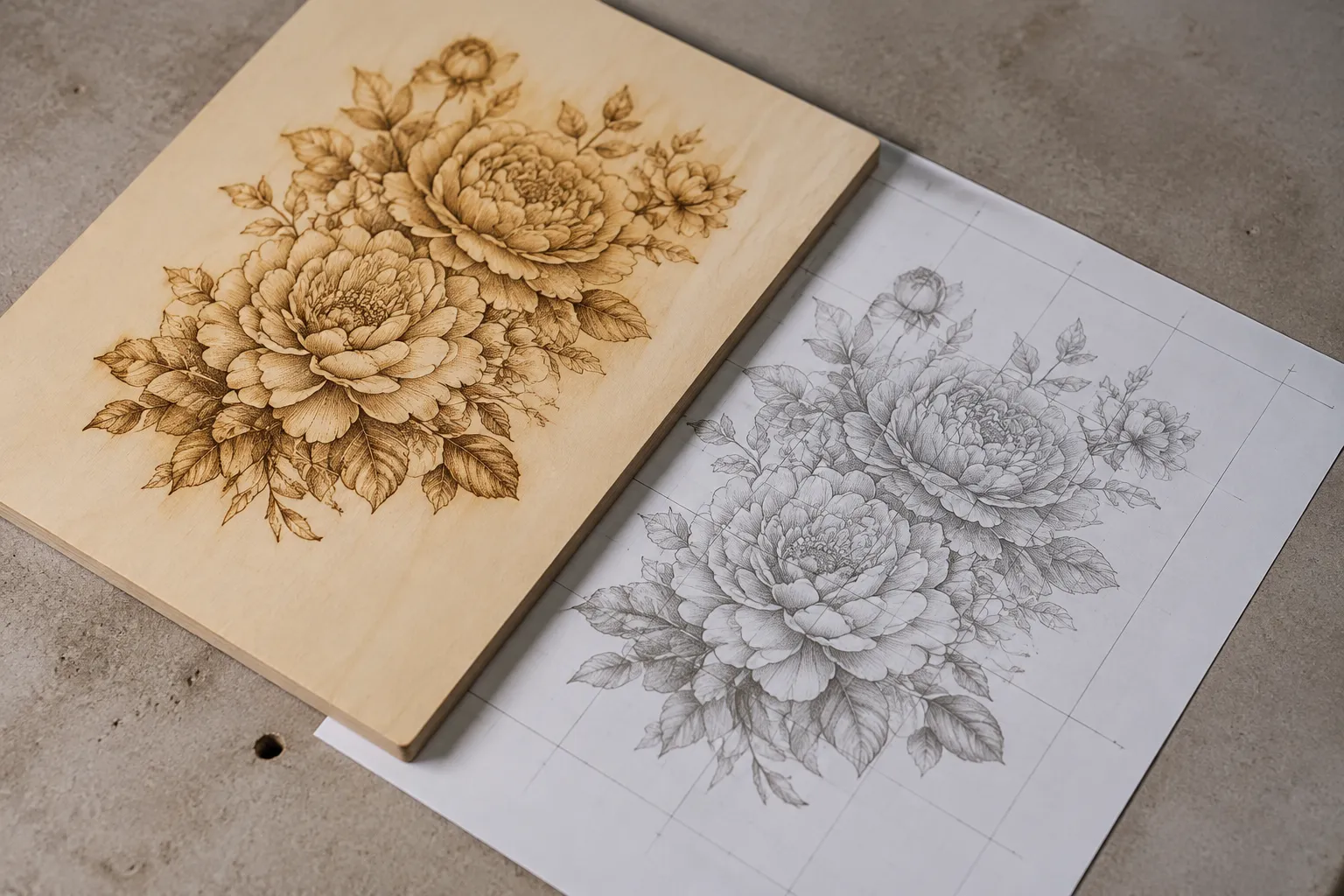
A bright patch may be glare. A missing shadow may begin in the source image. A soft edge may reflect focus, motion, material texture, or image capture. The useful review question is: what visible cue is present, what can the photograph establish, and which check can resolve the uncertainty?
This distinction keeps a sample comparison useful during customer approval and shop handoff. It also prevents a concept preview, material-context mockup, or attractive product photograph from being treated as an approved production record.
Identify What the Image Records
Not every engraving image carries the same evidence. Label the asset before comparing it with another result.
Concept Preview
A concept preview shows intended artwork, composition, or tonal direction. It can support approval of a monogram, badge, plaque layout, or photographic subject.
It does not establish how the material will respond. Fine detail, shading, edge definition, and contrast remain provisional until the shop processes the artwork in the stated material and records the result.
Material-Context Mockup
A material-context mockup places artwork on a representation of a surface. It helps judge scale, placement, and visual balance.
It cannot prove engraving depth, residue, roughness, color change, or machine output. Treat its tonal appearance as a design reference rather than a test-piece record.
Photographed Sample
A photographed sample records a physical piece, but capture conditions still matter. Lighting direction, exposure, viewing angle, surface orientation, reflection, and camera processing can change what the image appears to show.
The photograph supports a visible comparison. It may not resolve depth, surface roughness, residue, deformation, or material integrity without additional inspection.
Path View
A path view shows how software or a machine workflow interprets the artwork. It can reveal missing contours, filled regions, broken bridges, unexpected gaps, or a different dithering pattern.
It cannot show the final surface appearance. A clean path view does not prove that the sample will retain the same detail or contrast.
Documented Test-Piece Record
A documented test-piece record connects an observed result with stated material, finish, machine or process context, image-processing path, and capture conditions.
It is the strongest comparison asset in this group, but it remains shop-dependent. One successful test does not establish universal settings, material compatibility, or identical results on another machine.
Compare Photos Under Consistent Conditions
Control the photograph before interpreting the engraving. Use consistent lighting and viewing angle where possible, and keep sample orientation, crop, and scale comparable.
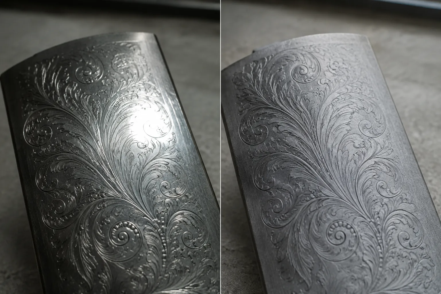
Record whether each surface is glossy, matte, coated, textured, curved, or naturally variable. Reflection can create a hotspot that looks like a missing mark, shallow area, or clipped highlight. A darker angle can make a groove appear deeper than the photograph establishes.
The comparison remains provisional when the images were captured under different conditions. Request a repeat photograph before routing the issue as a confirmed physical defect.
Glare in Engraving Photos
Visible cue: A bright streak or hotspot crosses the engraved area and changes the apparent contrast of nearby details.
What it may explain: Glare can obscure contours, shading, or small marks. It can make one part of a sample appear lighter without proving a change in engraving depth or material removal.
What the photo cannot establish: The image alone cannot determine whether the bright region is reflective surface light, a lighter material response, a shallow mark, or incomplete engraving.
Next check: Request a repeat photograph with consistent, diffuse lighting and a changed viewing angle. If the bright region moves while the physical sample remains unchanged, capture conditions become a stronger explanation. If the feature stays fixed, continue with source-file and physical checks.
Clipped Highlights
Visible cue: Light areas merge into an almost uniform white region, and surface detail disappears inside the brightest tones.
What it may explain: Exposure or tonal handling may have removed separation between light material and lightly engraved areas. The source image may also contain highlights with little usable contrast for engraving.
What the photo cannot establish: A clipped highlight does not prove that the laser removed too little material or that the sample lost detail during processing.
Next check: Review the original photograph and processed source file. Compare the highlight region before grayscale conversion, contrast adjustment, and dithering. Manufacturer guidance treats image sharpness, tonal range, contrast, grayscale conversion, and dithering as relevant preparation variables, but its resolution preference is source-specific.
Muddy Shadows
Visible cue: Dark regions merge, making counters, gaps, or adjacent contours difficult to separate.
What it may explain: The source image may have compressed shadow detail. Image processing may also have pushed several tones into one dark range. Material response can further reduce visible separation.
What the photo cannot establish: Muddy shadows do not identify whether the limitation began in the source image, software path, material surface, or physical process.
Next check: Compare the original image, grayscale or dithered working file, path view, and photographed sample in that order. Record where the detail first disappears. That location gives the shop a more useful revision target than a general request to improve quality.
Separate Source Limits From Process Variation
A photograph can show a difference without showing its first cause. Review the source file and physical sample as separate evidence.
Missing Shading in Engraving Samples
Visible cue: Broad shapes remain, but gradual tonal changes disappear. Faces, folds, gradients, or photographic transitions look flatter than expected.
Possible source limitation: The input image may lack tonal separation, or grayscale conversion may compress important midtones. Dithering can also change how continuous tones become marks.
Possible process limitation: Material response, focus, scan strategy, surface finish, and other shop-dependent variables can affect tonal separation. Measurement-oriented wood engraving studies can frame how the input graphic and natural material structure influence a result, but they do not establish a rule for every material or machine.
Next check: Inspect the source image and path view before changing machine variables. If the shading exists in both but not in the sample, request the exact material, finish, machine, lens, process label, and documented test context.
Brightness, Contrast, and Saturation
Readers may describe a sample as too bright, too dark, low contrast, or lacking saturation. These observations are useful, but they do not identify one correction.
Brightness may describe the photograph, source image, or physical surface. Contrast may refer to tonal separation in the artwork or visual separation created by the material. Saturation may matter in a color photograph while becoming less informative after grayscale conversion.
- “The light region disappears in the photograph” points toward exposure and glare review.
- “The source file lacks separation between adjacent tones” points toward image preparation.
- “The path view contains the tones, but the sample merges them” points toward material and process review.
- “The sample changes appearance across viewing angles” points toward reflection and repeat photography.
Brightness, contrast, saturation, DPI, and dithering are workflow variables, not universal settings. Their effect depends on the source, software, material, machine, and process.
Resolution and DPI
A high-resolution source image does not guarantee retained detail. DPI describes one part of image preparation or machine workflow, not the complete physical result.
Supplied manufacturer guidance can inform a preparation conversation, but it cannot establish final quality across different machines, lenses, materials, or workflows. For handoff, record source resolution, working resolution, grayscale or dithering method, resizing, and sharpening. Compare the path view with a documented sample rather than judging the number alone.
Use Edge Cues Carefully
Edges are often easier to compare than broad tonal regions. They also expose several different dependencies.
Edge Softness in Engraving Photos
Visible cue: A contour appears blurred, feathered, wider, or less defined than the intended artwork.
Possible capture explanation: Focus, camera distance, motion, reflection, or compression can soften the photograph. A textured or uneven surface can make a clean edge look irregular.
Possible process explanation: Focus, optics, scan strategy, line width, material response, and mechanical variation may affect the physical edge. These factors are context-dependent rather than interchangeable causes.
Next check: Compare the source contour with the path view. Then inspect the physical sample under consistent lighting, requesting a closer documented image or physical inspection where needed. A photograph alone cannot establish actual edge width or depth.
Tonal Banding
Visible cue: A gradient appears as steps, stripes, patches, or repeated tonal bands.
Possible source explanation: Grayscale conversion, dithering, resizing, or limited tonal separation may introduce a pattern before production.
Possible process explanation: Scan strategy, surface variation, or uneven response may create repeated changes across the sample. Alignment with scan direction warrants shop-side review, but the photograph does not prove the mechanism.
Next check: Compare the source file, processed file, path view, and sample at the same scale. Ask whether the bands repeat in the same orientation on the physical piece. A labeled test matrix may help separate image-processing behavior from process variation.
Missing or Broken Fine Details
Visible cue: Small bridges, counters, gaps, or interior marks disappear.
What it may explain: The source image may be too small or low-contrast for the intended scale. Path conversion may close gaps or remove narrow strokes. Material texture and process variation may further reduce separation.
Next check: Isolate the affected feature in the vector or path view. Confirm its intended scale and minimum gap with the shop. The revision may involve source preparation, vector cleanup, a simplified contour, or a material-specific test.
Do not infer a machine defect from one lost detail. Route the observation to the earliest stage where it can be confirmed.
Request Evidence a Photograph Cannot Supply
Residue or Surface Roughness
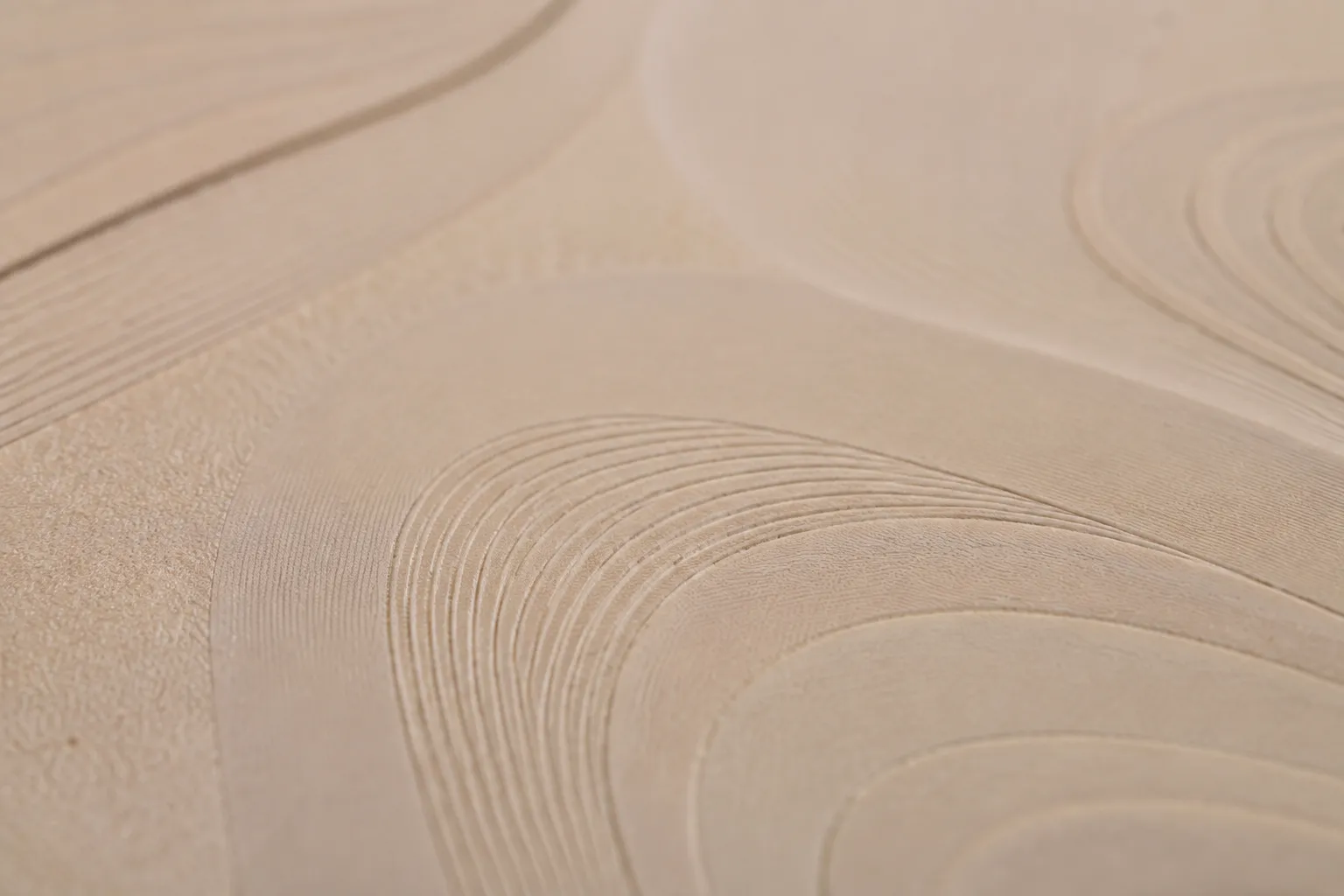
A dark halo, pale deposit, cloudy region, or uneven texture may be visible in a photograph. Reflection, dust, surface finish, sharpening, or compression can also create or exaggerate the appearance.
The image does not reliably establish residue, roughness, or the condition of surrounding material. When the distinction affects approval, request the exact material and finish, surface-preparation information, and physical inspection or documented close-up.
Depth Change or Deformation
A photograph may suggest a darker groove, raised edge, uneven plane, or local deformation. It cannot reliably measure depth or confirm a change in surface geometry.
If depth or deformation matters to the handoff, request a documented test-piece record or suitable physical measurement. Keep the equipment, material, lens, and process conditions attached to that record.
Permanent or Durable Appearance
A photograph records appearance at one point in time. It does not establish wear behavior, coating compatibility, material integrity, or long-term appearance.
Those questions belong with the relevant manufacturer, supplier, shop operator, rights holder, or qualified local professional. They should not be inferred from a clean sample photograph or a market phrase such as “durable” or “damage-free.”
Route the Comparison Through Four Explanations
A four-part triage model keeps the review focused and assigns the next check.
1. Capture Artifact
The visible difference changes with lighting, exposure, angle, reflection, crop, or camera processing.
Confirm with: A repeat photograph under consistent conditions.
Handoff status: Provisional until the images are comparable.
2. Source-Image Limitation
The original or processed artwork lacks the tonal range, sharpness, separation, or detail visible in the requested result.
Confirm with: Original-file review, grayscale review, processing history, and path inspection.
Handoff status: A design or preparation issue unless the shop identifies a later-stage change.
3. Process Variation
The source and path contain the intended feature, but the physical sample presents it inconsistently.
Confirm with: Exact material and finish, machine and lens context, process label, orientation, repeat photography, or a documented test matrix.
Handoff status: Shop-dependent and unresolved until the relevant context is recorded.
4. Confirmed Physical Defect
The same physical anomaly remains under controlled viewing and is supported by inspection or a documented test record.
Confirm with: Repeat observation, physical inspection, measurement where relevant, and comparison against approved artwork or stated acceptance criteria.
Handoff status: Record the affected area, material, process context, requested revision, and disposition.
This sequence avoids assigning blame too early. It gives the shop a clear next action instead of a vague request to improve the result.
Build a Useful Photographed Sample Comparison
A comparison sheet should preserve enough context to explain the difference later.
- Artwork version and original source file.
- Grayscale, brightness, contrast, saturation, resizing, and dithering steps.
- Working resolution or DPI, without treating it as a universal target.
- Material, finish, surface orientation, and approximate sample scale.
- Machine, lens, process type, and relevant shop context.
- Lighting direction, exposure, viewing angle, and camera distance.
- Asset type: concept preview, mockup, photographed sample, path view, or test-piece record.
- Visible cue under review and explanation currently considered likely.
- Check still required before approval.
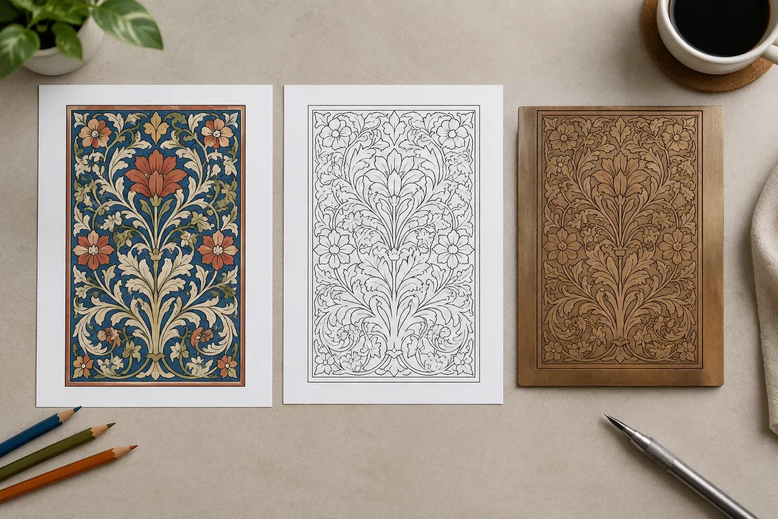
Use paired images where possible: original source beside processed source, processed source beside path view, and path view beside photographed sample. Keep crop and orientation consistent so the comparison shows a real change rather than a change in presentation.
For a product collection, compare the same feature across samples. A repeated monogram counter, border stroke, facial highlight, or badge gap can reveal whether the issue follows the artwork, material, or process.
Make the Handoff Decision
Approve the visual direction when composition, scale, key contours, and tonal intent are clear.
Mark the file provisional when the photograph is inconsistent, the source and path have not been reviewed together, or glare, exposure, or reflection could explain the visible cue.
Route the issue to the shop when the path contains the intended detail but the physical sample does not, or when material, finish, focus, process, depth, roughness, or surface preparation may change the interpretation.
Request a documented test piece or measurement when the decision depends on physical depth, roughness, residue, deformation, material integrity, or repeatability. A mockup or single attractive photograph cannot replace that evidence.
Questions to Send With the Review
- Was this image captured as a concept preview, mockup, photographed sample, path view, or documented test-piece record?
- Were the comparison photos taken under consistent lighting, exposure, angle, and surface orientation?
- Does the missing detail exist in the original file and processed working file?
- Does the path view retain the affected contour, gap, counter, or tonal region?
- What exact material and finish are shown?
- What machine, lens, process type, and shop context produced the sample?
- Is the visible difference confirmed on the physical piece, or only visible in the photograph?
- Would a repeat photograph, physical inspection, or labeled test matrix resolve the issue?
- Which information is decided, which remains provisional, and which depends on the shop?
These questions keep evidence ownership visible. The designer can document the artwork and image-processing path. The shop supplies exact production context and physical confirmation. The customer can approve the visible design direction without treating an unresolved photograph as proof.
FAQ: Photographed Laser Engraving Results
Can glare make an engraving look defective?
Yes. Glare can obscure surface detail or change apparent contrast, but it does not establish a physical defect. Repeat the photograph under consistent lighting and a different viewing angle first.
Why can a sample lose shading when the source image looks detailed?
The limitation may begin in the source image, grayscale conversion, contrast handling, dithering, path generation, material response, or process conditions. Review each stage in sequence instead of changing DPI or machine variables by assumption.
Does high DPI prove better engraving detail?
No. DPI describes one part of image preparation or machine workflow. The result also depends on the source, processing, material, machine, lens, focus, and documented process context.
Can a sample photograph prove engraving depth?
No. A photograph may suggest a depth-related difference, but it cannot reliably measure depth. Request physical inspection or documented measurement when depth affects approval.
What is the difference between a photographed sample and a mockup?
A photographed sample records a physical piece. A mockup represents how artwork may appear in a material context. Neither is universal production proof, and a mockup cannot substitute for a documented test.
When should the shop receive the issue?
Route it to the shop when the source file and path view retain the intended detail, but the physical sample changes it. Include the exact material, finish, machine or process context, image-processing path, and comparable photographs.
What should be called a confirmed defect?
Use that label only after the anomaly remains under controlled viewing and is supported by physical inspection or a documented test record. Until then, describe the visible cue and keep its cause unresolved.
A photographed comparison is most useful when it narrows the next decision. Name what the image shows, separate appearance from physical evidence, review the source and path, record material and process context, then request the smallest repeat check that can resolve the uncertainty.
Sources
- The Ultimate Guide to Laser Photo Engraving & Machine Selection
- A Method for Measuring the Quality of Graphic Transfer to Materials with Variable Dimensions (Wood)
- Crafting pixels in wood: understanding the interplay of technologies and visual perception in wooden photo engraving
- Improve Laser Engraving Quality with These 5 Simple Tips
- Surface Preparation Process before Laser Engraving on Materials
- Laser Cutter Safety